

How to Install BFM® fittings: 8-Step Installation Guide
Here’s how to take an installation from the first site review through the final fit check.
1. Identify the connection and operating conditions
Walk the line and record what the connection does. Is it stationary and in line? Are the pipes offset? Does a sifter or other piece of equipment vibrate or oscillate? A connection with movement needs a different connector length and installation gap than a stationary one.
Also note the product being conveyed and the operating conditions. These details help determine which connector material and configuration are appropriate. If you’re converting several connections, identify where you can use the same sizes to simplify ordering and spare-part inventory.
2. Measure available space and pipe diameters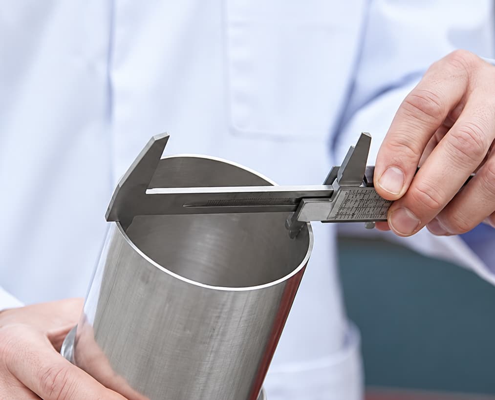
Measure the full space between the two connection points, including any pipework that could be shortened during the installation. Then measure the diameter at both ends. If the diameters differ, consider whether the pipework can be adapted to use matching spigots and a standard connector.
Record the BFM® fitting dimensions for each location before ordering, including the available space and both connection diameters. A sketch or photo showing the upper and lower connection points will make it easier to review the proposed fit with your maintenance team or PSI.
3. Check alignment and equipment movement
Plan to straighten angled pipework and align the connection points where practical. If an offset must remain, measure it rather than assuming the connector will accommodate it.
For moving equipment, measure the greatest movement from a fixed reference point. Check the equipment during startup and shutdown so you capture the range it actually travels. If there is vertical movement as well as horizontal movement, seek application-specific guidance: our standard installation gap calculator is designed for horizontal movement, and vertical movement requires an adjustment.
4. Calculate connector length and installation gap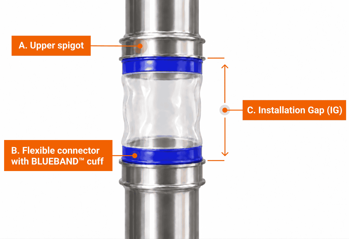
Use the BFM® Installation Gap Calculator with your measurements, or review the application with PSI. The installation gap is the space between the two spigot heads. It is normally slightly shorter than the connector length to allow the connector to be installed and removed. Offset and movement affect the gap you need, so determine the installation gap before fixing the spigots in place.
This is the point in your decision process to confirm the spigot diameters, connector material and length, and any special requirements with PSI. We can help review measurements for individual connections or document sizes and configurations across a larger installation.
5. Select the spigot attachment method
BFM® spigots are commonly welded to the pipework or equipment. For modular piping with quick-release clamps, lipped spigots may be an option. Spigots can also be welded to ferrules or flanges in a fabrication shop ahead of a shutdown. Whichever method you choose, plan the final spigot positions around the calculated installation gap.
If space is tight, the spigot tails may be shortened. Take care during fabrication: heat distortion of the spigot head can affect how the connector cuff fits and seals. Follow PSI’s spigot welding guidance and your facility’s welding and hygiene requirements.
6. Install the spigots and verify the installation gap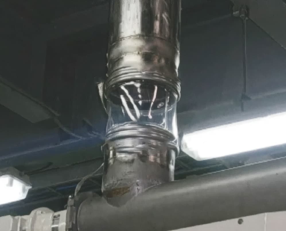
With the equipment prepared under your plant’s procedures, position the spigots at the planned gap. For a welded installation, align the spigot to the pipe, tack weld, spot check your measurements, peen the tacked joint, and then complete and finish the weld. Control heat input to avoid distortion, especially on larger spigots.
Before fitting the connector, remeasure the installed gap and check the alignment. Correcting a positioning issue now is easier than trying to make the connector compensate for it.
7. Snap the BFM® connector into place
Check that the spigots and connector cuffs are clean and ready for use. To fit a standard BFM® connector, seat the back of the BLUEBAND® into the spigot ridges. Use your thumbs to form the sleeve into a kidney shape, position the rest of it inside the spigot in line with the ridges, and release it. Repeat at the other end, then check that both BLUEBANDS® are fully seated. Standard connectors snap in without clamps or tools.
8. Inspect the connector fit and document the installation
Before returning the line to service, check that the connector is seated evenly at both ends, is not twisted, and has room to accommodate any movement if required. Follow your facility’s commissioning procedure to check the connection under its normal operating conditions.
Finally, record the connector specification and location for future replacements. If a cuff does not snap in completely or the installed connector looks strained, stop and recheck the seating, spigot condition, alignment, and installation gap. PSI’s installation resources provide further instructions and troubleshooting help.
Planning a new installation or converting several connections?
Contact Powder-Solutions, Inc. to review your measurements, connector selection, and installation approach before the work begins.